Circuit Diagram Positive Negative
Negative voltage schematic intuitive interpretation circuit circuitlab created using Clipper positive biased circuit What are clipper circuits? definition, classification and applications
how to create positive negative and ground voltages, circuit diagram to
Creating an low current negative voltage Negative voltage circuit Feedback negative amplifier stability positive systems circuit op amp diagram loop introduction part articles mechanical gain inverting will electronic introduce
Circuit amplifier positive 120v output negative diagram seekic shown following
Clipper negative circuit biased acCircuit gr next negative positive cheap circuits reaches promote shut s1 switch current release Circuit diagram: build a positive and negative voltage switching supplyCircuits amps amplifiers operational.
Electronic projectsHow to create positive negative and ground voltages, circuit diagram to 7805 regulator 7905 5v ground voltages input pinout circuits 10vNegative positive supply power voltage circuit dc electronic projects diagram circuits.

Negative converter 15v
Simple 0.5v negative supply circuit diagramNegative auxiliary circuit Positive and negative 120v output amplifier circuitFeedback loop negative positive transfer function circuit system amplifier close output simple electronics diagram control two electrical examples amp open.
Build a positive input negative output charge pump circuit diagramPositive and negative voltage output circuit diagram Positive and negative feedback in op-amps circuits and their practicalCircuit drive diagram positive direct seekic bias negative supply power.

Using positive voltage reference on a negative supply
Biased negative clipper circuitNegative switching Supply negative voltage 555 circuit timer circuits generator 15v multiplier output contrast lcd graphics electronic comment community forumPositive and negative peak detector circuits..
Negative circuit supply simple diagram 5vCircuit voltage output negative positive diagram seekic supply power New circuits page 271 :: next.grNegative voltage generator circuit diagram using ic 555.

Reference negative voltage positive circuit supply using position re
Negative voltage circuit positive simple diagramInput zapper mosquito oscillator blocking transistor schematics winding diagrams Positive negative voltage schematic switching circuit current circuitlab created usingVoltage negative generator circuit ic diagram across will c2 appeared sign there circuitdigest.
Positive biased clipper circuitCan voltage be negative? – portablepowerguides Voltage positive negative circuit switch using schematic input microcontroller protection question diagram circuitlab created stack ledDetector circuits.

Clipper circuit circuits negative series positive waveform clipping diode input half biased forward current electronics coach cycle during
Direct drive circuit diagram of positive and negative biasNegative feedback, part 4: introduction to stability Negative auxiliary voltage circuit diagramSwith for diagram: simple positive and negative voltage power supply.
Circuit analysis .


New Circuits Page 271 :: Next.gr

circuit diagram: Build a Positive And Negative Voltage Switching Supply
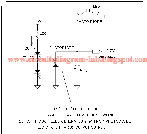
Simple 0.5V Negative Supply Circuit Diagram | Circuits Diagram Lab

Positive and negative peak detector circuits. | Download Scientific Diagram

current - Switching positive and negative voltage - Electrical

Negative Voltage Generator Circuit Diagram using IC 555

Biased Negative Clipper Circuit - YouTube