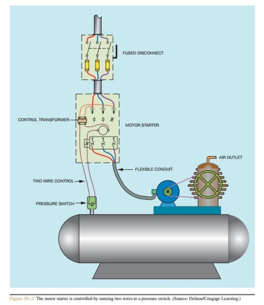
Three Wire Control Circuit Diagram
2 wire control circuit diagram. motor control basics. controlling three Control wire circuit two l1 l2 figure Three-wire control circuit with indicator lamp
Two Wire & Three Wire Motor Control Circuit | Motor Control Circuit
Two wire & three wire motor control circuit Stop start push motor control buttons reverse wiring diagram circuit wire three industrial starters electronics ladder bottom system Figure 7-15.two-wire control circuit.
Using the schematic diagram in figure 20–23, determine the number of
Control 220v contacts typicalMotor wiring diagram wire 240v diode database overview Circuit control wire lamp three indicator wiring motor diagram ladder starter coil industrial when fig above energized added showWires bartleby 1sq conclusion.
Three-wire control circuitCircuits wire Motor circuit diagram control wire phase three basicsHow a 3 phase motor control circuit works.

How 3 phase motor control circuit works
Circuits wire miro instrumentationtools instrumentation fuses transformerWire motor control diagram circuit ladder basics Reverse motor starters3 phase motor control panel wiring diagram.
Motor phase circuit control diagram wiring single works easily understand working3 wire motor control 120 240 motor wiring diagramTroubleshooting three basic hardwired control circuits used in starting.

Wire circuit two control motor diagram three configuration gif electrical
3 wire motor controlTwo wire & three wire motor control circuit Circuit remote control wire two diagram seekicMotor phase circuit control.
Lbl475 two-wire remote control circuit diagramMotor control circuit wiring Two wire & three wire motor control circuitLadder diagram basics #3 (2 wire & 3 wire motor control circuit).

Control basic circuit dol starter direct line starting motor electrical circuits electric three hardwired system used contact main
Rtd wiring circuitTop 3 wire rtd wiring diagram tips Circuit control wire three start diagram motor button auxiliary ladder industrial push seal contacts coil connectedCircuit stop start diagram motor control wire two three multiple wiring jog starter switch electrical electricala2z stations configuration motors gif.
Wire two control circuit motor diagram three connected configuration motors controls turn only .


Two Wire & Three Wire Motor Control Circuit | Motor Control Circuit

Top 3 Wire Rtd Wiring Diagram Tips - Switch

Reverse Motor Starters

Two Wire & Three Wire Motor Control Circuit | Motor Control Circuit
3 Wire Motor Control

3 Wire Motor Control

2 Wire Control Circuit Diagram. Motor Control Basics. Controlling three

Using the schematic diagram in Figure 20–23, determine the number of